|
|
 기타장비 기타장비
랙케이스*브라켓*스피커
스탠드*마이크박스*마이크선*콘넥터외 |
|
|
|
|
 |
|
|
|
|
|
|
|
제품정보
|
HOME -> 제품소개 -> 제품정보
|
|
 제품명 제품명 |
4ch 컴프레서/리미터 |
|
| 제조사 |
DBX |
| 모델명 |
1046 |
|
| 제품개요 |
상품명 : 1046
판매가 : 850,000 원
제조사 : DBX
간략설명 : 4ch 컴프레서/리미터
|
|
 |
 |
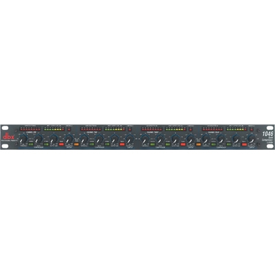
1046
Quad Compressor Limiter는 4채널에 독립적으로 클래식 Overeasy나 Hard Knee 컴프레션 기능을 사용할수 있으며, 각 채널을 별도의 목적을 위해서 독립적으로 사용할 수 있는 제품입니다. 또한, 리미팅 Peak Stop Plus 회로는 스피커에 대한 데미지에 가능성을 줄이고, 가변형 +4dbu나 -10dbv 동작 레벨을 통해
다른 장비와의 연결을 용이하게 하고 있습니다.
오늘날의 레코딩과 사운드 보강 환경에서, 질 높고 사용하기 쉬운 멀티 채널의 컴프레서에 대하여 수많은 필요성이 있다. 이러한 기세를 꺾을 역할을 하기 위한 dbx 1046이 여기에 있다.
각각의 4채널은 별도의 목적을 위해서 각각의 채널을 연결할 뿐만 아니라, 우리의 클래식 OverEasy나 hard knee 컴프레션 사이에서 개인적으로 선택할 수 있도록 해준다.
게다가, 시장에서 가장 넓은 리미팅 기술인 우리의 PeakStopPlus 회로는 스피커에 대해서 걱정하는 맘을 자유롭게 하여, 음악에 집중할 수 있도록 해준다.
다른 장치와 쉬운 인터페이싱 때문에, 1046의 각 채널들은 균형잡히고 금도금된 XLR, 1/4” 입력과 출력, 바뀔 수 있는 +4dBu나 –10DbV 동작 레벨을 이용한다.
1046은 우리의 표준 세팅 디자인, 예술의 상태인 제조 기술과 미래를 보는 사운드 질과 상호 합동한다.
SPECIFICATION
1046
Inputs
XLR and 1/4' TRS (Pin 2 and tip hot)
Balanced > 40 k Ohm, unbalanced >20 k Ohm
> +22 dBu balanced or unbalanced
Outputs
XLR and 1/4' TRS (Pin 2 and tip hot)
Balanced 30 Ohm, unbalanced 15 Ohm
> +22 dBm balanced, > +20 dBm unbalanced
Frequency Response
0.35 Hz to 90 kHz, +0/-3 dB
Dynamic Range
> 118 dB, unweighted
Thd+Noise
0.008% typical at +4 dBu, 1 kHz unity gain
0.08% typical at +20 dBu, 1 kHz, unity gain
< 0.1% any amount of compression up to 40 dB, 1 kHz
Dimensions
4.4(H) × 48.3(W) × 20.1(D) cm
Weight
2.4 kg
INPUT
Connectors: XLR and 1/4' TRS (Pin 2 and tip hot)
Type: Electronically balanced/unbalanced, RF filtered
Impedance: Balanced > 40 kOhm, unbalanced >20 kOhm
Max Input Level: > +22 dBu balanced or unbalanced
CMRR: Typically >50 dB at 1 kHz
OUTPUT
Connectors: XLR and 1/4' TRS (Pin 2 and tip hot)
Type: Servo-balanced/unbalanced, RF filtered
Impedance: Balanced 30 Ohm, unbalanced 15 Ohm
Max Output Level: > +22 dBm balanced, > +20 dBm unbalanced
SYSTEM PERFORMANCE
Bandwidth: 20 Hz to 20 kHz, +0/-0.5 dB
Frequency Response: 0.35 Hz to 90 kHz, +0/-3 dB
Noise: < -96 dBu, unweighted, 22 kHz measurement bandwidth
Dynamic Range: > 118 dB, unweighted
THD+Noise: 0.008% typical at +4 dBu, 1 kHz unity gain
0.08% typical at +20 dBu, 1 kHz, unity gain
< 0.1% any amount of compression up to 40 dB, 1 kHz
IMD: < 0.1% SMPTE
Interchannel Crosstalk: < -80 dB 20 Hz to 20 kHz
Stereo Coupling: True RMS Power Summing
COMPRESSOR
Threshold Range: -40 dBu to +20 dBu
Ratio: 1:1 to infinity:1
Threshold Characteristic: Selectable OverEasy? or hard knee
Attack/Release Characteristic: AutoDynamic™
Attack Time: Program-dependent
Release Time: Program-dependent
Output Gain: -20 to +20 dB
LIMITER
Threshold Range: 0 dBu to +24 dBu (off)
Ratio: infinity:1
Limiter Type: PeakStopPlus? two-stage limiter
Stage 1: PeakStop? brickwall limiter
Attack Time: Zero
Release Time: Zero
Stage 2: Predictive intelligent program limiter
Attack Time: Program-dependent
Release Time: Program-dependent
FUNCTION SWITCHES
OverEasy?: Activates the OverEasy compression function.
I/O Meter: Switches between monitoring input and output levels on the Input/Output Level meter.
Bypass: Activates the direct input-to-output hard-wire bypass.
OPERATING LEVEL
(rear panel): Switches the nominal operating level between -10 dBV and +4 dBu simultaneously for both input and output levels.
ST Link: Links channels in stereo pairs. Channels One and Three become the master channels.
INDICATORS
Gain Reduction Meter: 8 segment LED bar graph at 1, 3, 6, 10, 15, 20, 25, and 30 dB
Input/Ouptut Meter: 8-segment LED bar graph at -24, -18, -12, -6, 0, +6, +12, and +18 dBu
PeakStop™: 1 LED to indicate PeakStop™ limiting
Function Switches: LED indicator for each front-panel switch
OPTIONS - Output Transformer
Per Channel: Jensen? JT-123-dbx or JT- 11-dbx, BCI RE- 123-dbx or RE-11-dbx
POWER SUPPLY
Operating Voltage: Switchable: 100-120 VAC 50-60 Hz or 200-240 VAC 50/60 Hz
Power Consumption: 20 Watts
Fuse: 100-120 VAC:250 mA Slow Blow
200-240 VAC:125 mA Type T
Mains Connection: IEC receptacle
PHYSICAL
Dimensions: 1.75'Hx19'Wx9'D (4.4cmx48.3cmx20.1cm)
Weight: 5.2 lbs. (2.4 kg)
Shipping Weight: 7.6 lbs. (3.5 kg)
Note: Specifications subject to change without notice.

|
 |
|
|
|


)
)


